Setelah semedi 1 -2 hari di kaki gunung Ciremai ini dia ....

Penjelasannya ???
Pasti rekan2 disini bisa memberikan penjelasannya . Believe it or not ....
Moderators: christoffel, scratcher


Code: Select all
/*********************************************
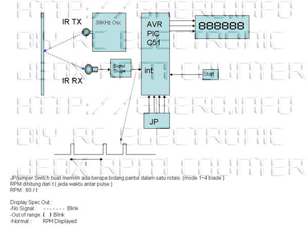
1st Project : RPM Counter
Author : Jan Thogersen
2nd Project : Touchless RPM Count
Author : Jedx @ Gaero
Chip type : 1st. AT2313, 2nd ATmega8
Clock frequency : 8,000000 MHz
Memory model : Tiny
Internal SRAM size : 128
External SRAM size : 0
Data Stack size : 32
*********************************************/
#include <mega8.h>
// Here is the definition of which port pin is used for which LED in the matrix.
// The following defines is the ROW in the matrix.
// These values can be changed to fit the PCB layout.
#define A 4
#define B 128
#define C 32
#define D 2
#define E 1
#define F 16
#define G 64
#define Dod 8
// The following defines is the COL in the matrix.
// These values can be changed to fit the PCB layout.
#define COL_A 0x011110b
#define COL_B 0x101110b
#define COL_C 0x110110b
#define COL_D 0x111010b
#define COL_E 0x111100b
// Definition of the 7 segment numbers
// A
// -----
// F | G | B
// |----|
// E | | C
// -----o
// D Dod
const unsigned char DIGITS[] = {
(A+B+C+D+E+F), // 0
(B+C), // 1
(A+B+G+E+D), // 2
(A+B+C+D+G), // 3
(B+C+F+G), // 4
(A+C+D+F+G), // 5
(A+C+D+E+F+G), // 6
(A+B+C), // 7
(A+B+C+D+E+F+G), // 8
(A+B+C+D+F+G), // 9
(0) // blank
};
const unsigned char COLUMS[] = {COL_A, COL_B, COL_C, COL_D,COL_E};
#define NumMeasures 2 // The output is a average of the X readings
unsigned char ucLEDS[5], ucLED_POS;
unsigned char ucCiffer[5];
unsigned int uiTempDigi, uiOutput;
unsigned long ulMeasuredTime;
unsigned char ucOutputOutOfRange;
unsigned long ulMeasured[NumMeasures];
unsigned char ucMeasuredPos;
// Timer 0 overflow interrupt service routine
interrupt [TIM0_OVF] void timer0_ovf_isr(void)
{
// Place your code here
// Here is the 7 segment matrix scanner.
TCNT0=0xF0; // This value can be changes to scan faster or slower.
PORTC = COLUMS[ucLED_POS];
PORTB = ucLEDS[ucLED_POS];
ucLED_POS++;
if (ucLED_POS == 5) ucLED_POS = 0;
}
// Timer 1 overflow interrupt service routine
interrupt [TIM1_OVF] void timer1_ovf_isr(void)
{
// Place your code here
ulMeasuredTime += 0x10000;
if (ucOutputOutOfRange > 0) ucOutputOutOfRange--;
}
// Timer 1 input capture interrupt service routine
interrupt [TIM1_CAPT] void timer1_capt_isr(void)
{
// Place your code here
if (ucOutputOutOfRange < 16) ucOutputOutOfRange+=4;
// Place the hardware timer value into the 32 bit accumulation.
ulMeasuredTime += ICR1;
TCNT1 = 0;
// The output is based on an average, so we save the measurements.
// This is not the best way to do it. I know that. But it was fast to code
// And I had enough RAM to do it. But a waste I know.
ulMeasured[ucMeasuredPos] = ulMeasuredTime;
ucMeasuredPos++;
if (ucMeasuredPos >= NumMeasures) ucMeasuredPos = 0;
ulMeasuredTime = 0;
}
// Declare your global variables here
char cTempCnt;
unsigned long ulSum;
void main(void)
{
// Declare your local variables here
// Input/Output Ports initialization
// Port B initialization
// Func0=Out Func1=Out Func2=Out Func3=Out Func4=Out Func5=Out Func6=Out Func7=Out
// State0=1 State1=1 State2=1 State3=1 State4=1 State5=1 State6=1 State7=1
PORTB=0xFF;
DDRB=0xFF;
// Port D initialization
// Func0=Out Func1=Out Func2=Out Func3=Out Func4=In Func5=In Func6=In
// State0=1 State1=1 State2=1 State3=1 State4=T State5=T State6=T
// PORTD=0x3C;
// DDRD=0x3C;
PORTC=0x1F;
DDRC=0x1F;
// Timer/Counter 0 initialization
// Clock source: System Clock
// Clock value: 31,250 kHz
TCCR0=0x04;
TCNT0=0x00;
// Timer/Counter 1 initialization
// Clock source: System Clock
// Clock value: 125,000 kHz
// Mode: Normal top=FFFFh
// OC1 output: Discon.
// Noise Canceler: On
// Input Capture on Faling Edge
TCCR1A=0x00;
TCCR1B=0x83;
TCNT1H=0x00;
TCNT1L=0x00;
OCR1AH=0x00;
OCR1AL=0x00;
// External Interrupt(s) initialization
// INT0: Off
// INT1: Off
// GIMSK=0x00;
MCUCR=0x00;
// Timer(s)/Counter(s) Interrupt(s) initialization
TIMSK=0x24;
// Analog Comparator initialization
// Analog Comparator: Off
// Analog Comparator Input Capture by Timer/Counter 1: Off
// Analog Comparator Output: Off
ACSR=0x80;
// Global enable interrupts
#asm("sei")
uiOutput = 0;
while (1) {
ulSum = 0;
// Calculate the average
for (cTempCnt = 0; cTempCnt < NumMeasures; cTempCnt++) ulSum += ulMeasured[cTempCnt];
uiOutput = (long)ulSum / NumMeasures;
// Calculate the RPM from the average time between pulses.
uiTempDigi = (long)(125000*60*NumMeasures) / ulSum;
// Place your code here
if (ucOutputOutOfRange > 4) { // > 4 then Ok Else to many overfloads...
// Check if the RPM is higner than we can show in the display else show "out of range" in the display.
if (uiTempDigi < 65535) {
// A simple binary to BCD converter.
for (cTempCnt = 5;cTempCnt > 0;cTempCnt--) {
ucCiffer[5 - cTempCnt] = (uiTempDigi % 10);
uiTempDigi = uiTempDigi / 10;
}
// Swap a leading zero with "blank"
for (cTempCnt = 4;(ucCiffer[cTempCnt] == 0) && (cTempCnt > 0);cTempCnt--) {
ucCiffer[cTempCnt] = 0x0A;
}
// convert the BCD value to port values.
for (cTempCnt = 0;cTempCnt < 5;cTempCnt++)
ucLEDS[cTempCnt] = ~DIGITS[ucCiffer[cTempCnt]];
// blink dot if signal in appears
if (PINC.6 == 0) ucLEDS[0] &= ~(Dod);
} else {
// out of range
if (PINC.6 == 0) ucLEDS[0] = ~(A+D+E+F+Dod);
else ucLEDS[0] = ~(A+D+E+F);
ucLEDS[1] = ~(G);
ucLEDS[2] = ~(G);
ucLEDS[3] = ~(A+B+C+D);
}
} else {
// no signal input.
if (PINC.6 == 0) ucLEDS[0] = ~(G+Dod);
else ucLEDS[0] = ~(G);
ucLEDS[1] = ~G;
ucLEDS[2] = ~G;
ucLEDS[3] = ~G;
}
};
}
Wind Raider wrote:Sistem yang pak Budi terapkan adalah dengan mengukur periode ; jadi lebih presisi .
Kita tunggu hasilnya pak .
p.s:
Watermarknya boleh juga nih ..
Oh ya , nama programnya lebih tepat NON CONTACT ketimbang TOUCHLESS


Wind Raider wrote:Setuju .. !!!!
Oh ya osilator 38 KHz gak mendng dibuat pakai program aja ?
Bisa hemat satu ic lagi
Ferry wrote:Xtal 38Khz banyak dipasaran biasa dipake untuk signal pilot stereo composite pembangkit FM stereo....kalo MCU tinggal program timingnya aja.